Ribbon type of cable is mostly used in computer and network systems. This solid type of wire conductor has unnoticed impacts in networks. The properties and the technical facts about this cable made it so unique.
solid wire cable
A cable having numerous conducting wires running parallel to each other on the same flat plane is referred to as a ribbon cable. This type of cable is also referred to as multi-wire planar cable. As a direct consequence of this, the cable is thin and wide. It was given its name because of the likeness it bore to a piece of ribbon. In most cases, the internal peripherals of a computer, such as the hard drives, CD drives, and floppy drives, are the ones that require ribbon cables.  They were also utilized for the purpose of external connection on certain earlier computer systems, such as the BBC Micro and Apple II series, respectively. The ribbon-like shape impedes computer cooling by disrupting airflow within the case. Additionally, the shape makes the cables awkward to handle, especially when there are a lot of them. As a result, round cables have almost entirely replaced ribbon cables for external connections, and they are increasingly being used internally as well. Cicoil Corporation, a firm with headquarters in Chatsworth, California, is credited with inventing the ribbon cable in the year 1956. The engineers of the company worked out how to use a new material called silicone rubber to’mold’ a flat cable that has numerous conductors of the same size. This was a big accomplishment. The cable was given the moniker “ribbon cable” due to the fact that it resembled a flat ribbon or duct tape. Ribbon cables enabled businesses such as IBM and Sperry/Univac to swap out their cumbersome and inflexible round cables for more streamlined and bendable ribbon cables. The mainframe computer industry was one of the earliest adopters of ribbon cables, which were utilized on card readers, card punching machines, and tape machines. After then, many different firms, including 3M, began producing ribbon cables. 3M was one of these companies. By standardizing the design and spacing of the wires, as well as the thickness of the insulation, in order for them to be easily terminated through the use of insulation displacement connectors, methods and materials were developed to simplify and reduce the cost of ribbon cables. This was accomplished by standardizing the design and spacing of the wires (IDC). Ribbon cables have been used for a long time in computers, printers, and a variety of other electronic equipment due to the fact that they are easy to use, have a low profile (when compared to contemporary alternatives), and are inexpensive due to the fact that they are standardized. Color-coding A red stripe is typically marked on one edge of the cable so that there is less of a chance of the connections being made backwards. The edge that has the stripe is always attached to pin 1 on the connection because this is the convention . This identification method is fine for cables that just consist of two or more IDC connectors with every plug connecting to every wire, but it is somewhat less helpful when individual wires or small groups of wires must be terminated separately. This identification method is fine for cables that just consist of two or more IDC plugs with every connector connecting to every wire. Ribbon-cable producers produced rainbow ribbon cable, which uses a repeating pattern of colors borrowed from the standard resistor color code, to make it easier to identify specific conductors within a cable.
solid electrical wire
This color scheme was borrowed from the resistor color code (Brown is pin 1 or pin 11 or pin 21, etc. Red is pin 2 or pin 12 or pin 22, etc.). Due to the fact that it has such a unique appearance, it is frequently lovingly referred to by its users as “hippie cable.” Sizes Cable made of ribbon with three connectors at each end The spacing between the conductors, also known as the pitch, and the number of conductors, sometimes known as ways, are the two numbers that are typically used to specify ribbon cables. The most common distance between rows is 0.05 inches (1.27 mm), which makes it possible to use a two-row connector with a distance between pins of 0.1 inches (2.54 mm). These kinds are utilized for a variety of different kinds of apparatus, in particular for making interconnections inside of an enclosure. Today, this size is utilized in the connections that connect floppy disk drives to personal computers, as well as in some older or specialized Parallel ATA cables. In most cases, the number of conductors is limited to a select few values due to the limited availability of standard connectors. These conductor counts include 4, 6, 8, 9, 10, 14, 15, 16, 18, 20, 24, 25, 26, 34, 37, 40, 50, 60, 64, and 80. Sometimes a wider width is employed, and then it is reduced to the size that is required; for instance, a 26-way IDC cable can have one wire easily removed in order to become a 25-way cable (before adding the connectors). The wire is often made of stranded copper wire and has a cross-sectional area that is either 0.32, 0.20, or 0.13 mm2 (22, 24, or 26 AWG). There are additional coarser and finer pitch options available for the cables. For example, the pitch of the high-speed ATA interface cable that is used for computer hard disk interfaces known as ULTRA-ATA is 0.025 inches (0.64 millimeters). In portable electronic equipment like laptops, you can find pitches as small as 0.3 mm; nevertheless, portable electronic equipment often makes use of flexible flat cables (FFC).  Connectors The primary use of ribbon cables is to enable mass termination to specially engineered IDC connectors. These connectors require that the ribbon cable be pushed onto a row of sharply forked contacts in order to function properly. When making a lead that needs to change wiring between the two connectors, for instance, only one end of the cable will be IDC revoked, with the other end being terminated in a regular crimp or solder-bucket connection. (The phrase “IDC connector” is widely used, while it is redundant — an example of RAS syndrome.) Most commonly, termination is done at both ends of the line, although sometimes. when trying to make a lead that needs to change wiring between IDC connectors are not designed to make it simple to disassemble and reuse them, despite the fact that this is sometimes possible to do with these connectors. The following is a list of common types of connectors that are available with IDC termination and are suited for ribbon cable: BT224 connections are utilized on ATA cables and are frequently referred to by their abbreviated name, “IDC connectors.” These connectors are also defined by the specifications BS9525-F0023, DIN41651, and MIL-C-83503. They are designed to connect with either a plug that was manufactured specifically for the purpose, or a grid of header pins with a spacing of 0.1 inch (2.54 mm). D-subminiature connectors are typically utilized for serial ports as well as printer interfaces. Micro ribbon connectors are typically utilized for 36-pin printer ports (IEEE 1284 – “Centronics”) and 50-pin SCSI port configurations. Connector with a DIN 41612 standard, utilized for Eurocard buses. PCB transition headers are distinguished by their two rows of pins, each of which is spaced in the same manner as BT244 connectors. With the intention of being soldered directly onto a printed circuit board. DIL headers have pins that are spaced in the same manner as the pins on typical DIL ICs. In most cases, this is employed in situations in which it is desired, for whatever reason, to replace an IC with a link to an external device (e.g., in-circuit emulators). Additionally able to function as a PCB transition header, particularly when placed on stripboard. (In order to successfully attach a header with conventional hole spacing to stripboard, you will need to cut the tracks in between the holes rather than on the holes themselves.) It is occasionally necessary for electronics hobbyists to solder ribbon cables when they are working on their personal computers or digital musical keyboards in order to “mod” (change) or “hack” (improve) them.
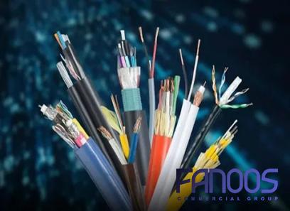
example of solid wire
Soldering ribbon cables can be difficult for a hobbyist who has not been trained as an electronics technician and who is not an expert in the field. Before soldering, some hobbyists remove the insulation from the wires with a very fine razor, then divide the wires into individual strands. Sandpaper of a finer grit is used by some hobbyists in order to remove the plastic insulation that covers the wires. The copper tracks are additionally primed by the sanding process. Then, the solder is guided into the track by the “tinned” soldering iron being touched onto the bare wire. Interference When it came to digital communication, using ribbon cable to connect two different devices was the best option. On the other hand, these cables present issues when seen from an analog perspective. In the early 1980s, the United States Ribbon cables were found to be extremely effective antennas by the Federal Communications Commission (FCC), which resulted in the dissemination of essentially random signals, often known as electromagnetic interference, across a large band of the electromagnetic spectrum. These unintentional signals have the potential to interfere with the reception of televisions in homes, causing “snow” to appear on the screen. The Federal Communications Commission (FCC) issued decrees and injunctions to the personal computer industry in order to place restrictions on the usage of ribbon cables to connect various components together. Inside the casing of a computer or peripheral device, “naked” ribbon wire could be utilized; however, any ribbon cable that connected two boxes together needed to be grounded. Because of this requirement, other alternatives were devised, such as ribbon cables wrapped in a copper braid barrier, which rendered it impossible to identify individual connectors or distinguish between them. When connected to an Apple II, these wires were routed through the holes on the back of the computer that led to the power supply. These holes served as a ground. Over time, ribbon connectors were gradually phased out in favor of a wide variety of circular cables with molded connectors, which were used for interconnecting various electronic components. Impedance The resultant impedance for any two adjacent wires within a ribbon cable with 26AWG wire, 0.050″ spacing, and common PVC insulation is between 110 and 130 ohms. The precise number will vary by a few percent due to the materials. Knowledge of the impedance is one step toward understanding and controlling interference that may be caused by ribbon cables. 
Your comment submitted.